MODULE 2
Title 5 Setbacks and Separations
What Every Board of Health Should Know
Introduction
Among the most common types of variance requests received by Boards
of Health are requests for relief from various setback or separation distances
required in Title 5. These horizontal setbacks (as denoted in Section
15.211 Minimum Setback Distances) and vertical separations requirements
(as denoted in Section 15.212: Depth to Groundwater), as well as
some of the prohibitions on placing septic systems in certain "sensitive"
areas are among the most crucial aspects of the code in respect to protecting
the public health and the environment.
While the terms "setback" and "separation" when
applied to life in general conjure up negative images, in the onsite sewage
world these terms merely refer to the position of a septic system relative
to a physical feature.
A Setback (also sometimes referred to as horizontal separation)
is the distance from a septic system component to a land-surface feature
such as a property line, wetland, private well, public water supply etc.
The various requirements for setbacks of septic tanks and leaching systems
are listed in 310 CMR 15.211 Minimum Setback Distances.
Vertical Separation (sometimes referred to simply as separation)
refers to the distance between the bottom of the leaching facility or soil
absorption system and the groundwater. Title 5 requirements in this regard
are contained in 310 CMR 15.212 Depth to Groundwater.
For
illustrations of the terms setback and vertical separation click here
This learning module primarily concerns itself with the issue of vertical
separation. It hopes to present the technical foundation on which proper
vertical separation distances are determined, and to give to you, Board
of Health members and agents, information by which you can determine whether
a particular variance request from these provision is appropriate for a
given situation. Horizontal Setbacks will be discussed in detail in
Module #3.
A Word about Variances before we go.
 You may wonder,
as you go through this module "Why am I learning all this stuff?".
While it's true that this course is probably showing you more than you
ever wanted to know about septic systems (or could ever discuss in polite
conversation), consider the following. When someone asks a Board of Health
for a variance, they are essentially charged with proving to the Board
that granting the variance will not materially affect the public health
and further, that the proposed system deficiency is compensated for somehow
by an action, design modification or extenuating site detail that provides
"a level of environmental protection that is at least equivalent to
that provided under 310 CMR 15.000"1.
How does a Board of Health fulfill their charge to protect the public health
and the environment by ensuring that this test is sufficiently met? They
either a) become savvy enough to understand the principles involved
and the technical foundation of those requirements, or b) they rely
on the proponent's claim that they meet the "test" and hope for
the best. If you chose "a", this bud's for you.
So let's get going. We begin first with TREATMENT 101, a discussion
of the treatment of effluent as it passes through the soil absorption system.
You may wish to review Module 1 before you start, particularly the discussion
of treatment in the septic tank. Following the discussion on treatment
in the unsaturated zone under the leaching facility, we will discuss groundwater
determination as it is carried out under the revised code. Finally, we
will summarize how the principles we learned can be brought to bear on
variance request from vertical separation (which also as we will see is
integrally connected with requests for reduction in leachfield size).

Again - Have Fun!
SEWAGE TREATMENT 101 (PART 2) - LIFE AFTER THE SEPTIC TANK.
For
an overview of the complete treatment process of a idealized standard Title
5 Septic system, click here
As we learned in the first module, a properly functioning septic tank
sends liquid wastes (with some finely ground solids - called "suspended
solids") to the leaching component of the system. This effluent typically
contains high densities of bacteria (> 108
per 100 mls of sample), and has the potential to contain pathogenic bacteria
and viruses at concentrations capable of transmitting disease. Chemically,
the effluent contains mineralized by-products of bacterial breakdown (ammonium,
phosphate, sulfates) and a dissolved organic "soup". Pipes and
structures convey the septic tank effluent to the soil interface, where
the ultimate goal is to spread the effluent out over the entire surface
area of the soil surrounding the soil absorption system. Now, let's take
the journey of the effluent as it departs the structures of the septic
system and passes first vertically through the soil (this Module), and
then horizontally away from the site with the groundwater (Module 3).
Biomat - The First Line of Defense
Although it can not do the job of treatment by itself, the vertical
separation between the bottom of the leaching facility and groundwater
(or in some instances an impermeable layer of bedrock) is the most important
characteristic of overall system design for preventing disease transmission.
To understand the truth in this statement, we first need to understand
what are the important features in this area that affect treatment and
how they are modified with different design changes. So let's start first,
where the action is relative to waste treatment - the soil particle surface!
As septic tank effluent is distributed onto the gravel aggregate and
the surrounding soil at the leaching facility-native soil interface, it
encounters a mini-ecosystem that has developed on each soil grain. In the
immediate area where the installed leaching components of the septic system
contact the native soil, a relatively dense sewage-digesting community
of organisms develops that is known as the biological mat or "biomat"
for short. The biomat is a very important feature of a properly functioning
system. Ideally, this area, which varies in thickness, contains a diverse
community of bacteria, fungi, protozoa (small one-celled animals that eat
bacteria), and even nematodes (small wormlike organisms that eat anything
they can get). These organisms are not necessarily pathogenic (capable
of transmitting disease in humans). Many of them are naturally-occurring
microbes, species of which have been breaking down larger organic molecules
for eons. In fact, if there weren't such organisms, we would be knee high
in our own wastes and garbage in no time. These organisms best treat wastes
where the conditions are aerobic (in the presence of oxygen).
The main thing to remember about these treatment organisms is that they
live, for the most part, on the soil particle surface. They remove
contaminants from the septic tank effluent as it passes over and through
their neighborhoods (the grain surface).
The biomat serves two very important functions. Foremost it supports
bacteria that breakdown and change wastes into soluble components that
can be carried away with the liquid. The protozoan community, made up of
mobile and voracious organisms, actively crop the sewage-digesting bacteria,
keeping their populations healthy, and as an added benefit also eat many
of the pathogenic bacteria that come from the septic tank. Many
of these pathogenic bacteria following passage through the anaerobic septic
tank that is relatively devoid of predators, now find themselves in an
environment where they are not adapted to feed, and hence become food themselves.
As for the pathogenic viruses? No such luck! Since viruses have no nutritional
requirements, they can persist for extended periods until their protein
coatings or genetic material is destabilized or broken down. Virus persistence
in the biomat is dependent on a number of factors including temperature,
pH, moisture content, presence of oxygen etc., and is type-specific. Additionally,
the small size of viruses may allow their passage through the biomat into
the underlying soil. Viruses will be discussed in detail later.
| Under anaerobic conditions bacteria can not completely break the wastes
down, leaving excess material to clog the pore space. In addition, protozoan
that would otherwise keep the bacterial community "healthy",
have trouble breathing and can not survive. |
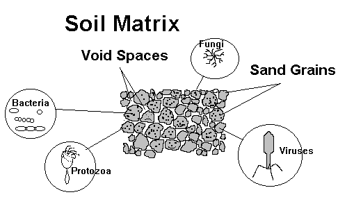
So, to summarize; the soil beneath a leaching facility is a matrix made
up the grains of soil, the void spaces, moisture, and the organisms living
on the surface of the soil grains. Treatment of the wastes occurs as it
passes over and through the areas where the organisms have colonized. The
number of organisms and their diversity depends on, among other factors,
the moisture conditions, the amount of oxygen, the amount of food or nutrients,
and the acidity.
 .
.
The second function of the biomat is to provide for unsaturated
flow of effluent from the leaching components to the groundwater! 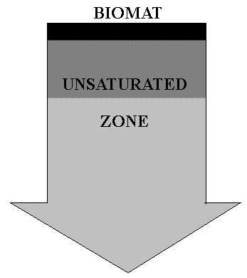
Beneath the biomat in a properly designed leaching facility is at least
4-5 ft of permeable material prior to encountering groundwater. In this
zone, in a decreasing gradient away from the bottom of the biomat,
is a community of organisms that further break down the wastes aerobically
(remember - in the presence of oxygen). The organisms in this area are
thinly distributed over the soil particles. Many of these organism
can not exist in the "harsher" environment of the biomat and
rely on the major strength of the sewage to be reduced there2.
For these communities to do their job properly, the effluent must pass
over them in a thin layer or film. To support these beneficial communities
of sewage digesting organisms, the void space between the soil particles
must also allow for the passage of necessary air containing oxygen. When
the void spaces between the grains of sand or other soil allows the passage
of effluent, and also allows the majority of the space to contain air,
we say that the flow through the soil is unsaturated. The biomat,
which forms a restrictive layer across the leaching component-soil interface
evens the flow across the entire infiltrative surface and provides for
unsaturated flow beneath the leaching facility. In the process, limited
ponding of effluent across the entire infiltrative surface occurs.
THE OBJECTIVE OF A LEACHING FACILITY IS TO PROVIDE
UNSATURATED FLOW OF EFFLUENT TO THE GROUNDWATER
THE OBJECTIVE OF A LEACHING FACILITY IS TO PROVIDE
UNSATURATED FLOW OF EFFLUENT TO THE GROUNDWATER
(YES THIS IS IMPORTANT!)
The reason for this performance objective is that unsaturated flow
of effluent through soils offers superior treatment. Again, unsaturated
flow results in superior treatment because the effluent passes in a thin
film over the biologically-active surface of the soil particles where it
receives maximum exposure to attached microorganisms. During saturated
flow, effluent fills the voids of the receiving soil and allows particulate
contaminants (such as bacteria and viruses) to pass untreated through the
large passageways between the soil particles. Since most of the biological
activity that transforms and treats wastes occurs in the thin surface film
of the soil particles, large passageway flow minimizes the treatment.
For
diagrams of saturated and unsaturated flow, click here
In unsaturated flow, the effluent passes through a tortuous path over
the soil particles. Bacteria and protozoa that grow on the soil particles
come in contact with the effluent and break the wastes down. A key thing
to remember is that unsaturated flow exposes the effluent to the biologically
active sites on the soil surfaces that transform the wastes and reduces
the pathogens.
So, how can we achieve aerobic and unsaturated
flow
beneath the soil absorption system ?
It's actually quite simple. Spread smaller amounts of effluent per given
area, closer to the surface of the ground where air exchange is more likely.
Sound familiar ? It should! Recent revisions to Title 5 requiring shallower
profile systems3
within three feet of the surface4,
with greatly reduced loading rates5
(Section 310 CMR 15.242: LTAR - Effluent Loading Rates) are designed
to encourage aerobic unsaturated flow. The reduction in allowable loading
rates is a large step toward recognizing the need for treatment in addition
to mere disposal.
Since Unsaturated Conditions Beneath the Leaching
Facility Are So Essential to Good Treatment,
How do Septic Systems that Conform to the Revised
Title 5 Promote the Necessary Unsaturated Flow Beneath their Leaching Facility
?
Good Question !
We have seen that in order to get the most out of the soil absorption
system relative to treatment, the septic tank effluent must be evenly
distributed over the maximum amount of infiltrative surface. Does this
happen in a regular gravity-fed6
leachfield ? Yes and No!
Even in the best constructed gravity-fed system, effluent in a newly-constructed
system spills out onto only a limited portion of the infiltrative surface
area. As the biomat forms, that limited area becomes somewhat clogged and
less infiltrative, and the effluent spills to adjacent areas. This process
continues until the entire infiltrative surface of the soil absorption
system seals to some extent. This process has been variously called progressive
maturation, progressive clogging, progressive biological mat formation,
and even progressive "failure" .
For
illustrations of the progressive maturation and failure of leaching chambers,
click here
In gravity-fed systems, unsaturated flows beneath the leaching facility
are supposedly maintained by the uniform restrictive action of the biomat.
The biomat evens and slows the vertical flow through the system when it
completely covers the infiltrative surface. In ideal situations, the continual
addition of cells, organisms and byproducts to the biomat is balanced by
the breakdown and digestion of dead cell mass and byproducts. Ideally ponding
in the system is maintained at a minimum, which promotes the continuance
of aerobic conditions. Under these conditions the biomat remains "healthy";
digesting and recycling the dead biomass, at the same rate that new biomass
is added during the waste-digestion process. This principle forms the basis
of the long term acceptance rate (LTAR) referred to in Section 15.242
LTAR - Effluent Loading Rates.
A logical question arising from this discussion is "How long does
it take the biomat to mature?" The answer depends on the strength
of the sewage, the soil characteristics, and other factors. Many have speculated
that in general six months up to one or two years may be necessary to form
a "mature" biomat. What happens in the meantime? Higher hydraulic
loadings in certain sections of the system occur until the vertical flows
are evened by the biomat, with less residence time of effluent in the treatment
zone, and possibly saturated flow to the groundwater.
In some situations, it is unlikely that the previously described scenario
of a progressive biomat formation that ultimately results in a stable biomat
and even unsaturated flow to the groundwater, will occur. What are these
situations ?
Seasonal Homes - In residences used seasonally and having gravity
fed leaching components, the beginning of each season will, in essence,
be a new starting point for the biomat formation. Higher localized hydraulic
loadings will mean less treatment and faster travel times from the bottom
of the leaching facility to the groundwater. Together these factors mean
less treatment.
High Intermittent Loading Situations - When there are wide variations
in the waste loads (volume or strength) to leaching facilities, the flow
pattern beneath the biomat can exhibit similar variations. Large intermittent
pulses of wastewater can cause localized "breakthrough" in portions
of the mat closest to the loading point. Because of this, larger systems
require pressure dosing as described below and in Module 1.
Are there any design features that can compensate for the lack of a
uniform biomat or intermittent pulses of high volume or high strength wastes?
We're glad you asked!
Dosing and Pressure Dosing
Dosing, as we learned in Module 1, is the practice of intermittently
applying septic tank effluent to a soil absorption system. The design guidelines
are presented in Section 15.252 Dosing. In traditional dosing, the
dosed volume is pumped to a distribution box for subsequent forced/gravity
flow to the leaching components. Although 4-inch diameter pipe is used
most commonly, it has been shown that smaller diameter pipe (minimum allowed
by Title 5 is 2-inch7)
provides more even distribution of effluent to the infiltrative surface.
The dosing with alternate resting of this type of system has been shown
to reduce the incidence of soil clogging failure and result in unsaturated
flow patterns from the leaching facility to the groundwater.
Dosed systems provide better distribution over the infiltrative surface
and more even and unsaturated flows from the bottom of the leachfield to
the groundwater. Accordingly, when faced with variance requests or local
upgrade approval requests relative to leaching area or distance to groundwater
in very environmentally sensitive areas, Boards of Health should consider
adopting a policy of requiring a dosed system to alleviate the problems
of simple gravity-fed system startup inefficiencies and to maximize use
of the treatment surface area.
Pressure Dosing - When you really want to get
the job done right!
Pressure dosing is distinguished from dosing by the fact that distribution
lines distribute effluent under pressure through small (1/4 -1/8")
holes. The system is designed to provide an equivalent discharge rate out
of each orifice using pressure, as opposed to relying on gravity flow.
Assuming openings are evenly spaced over the soil absorption system,
the infiltrative surface will be evenly loaded. This even loading of intermittently-applied
effluent can go a long way in compensating for the lack of the flow-evening
qualities of a biomat. In addition, this type of system may offer unsaturated
flow in all portions of a leaching facility right from day-1 of operation.
What do other experts have to say ?
In its Technical Evaluation of Title 5, DeFeo, Wait & Associates,
Inc. stated
"Dosing and resting of any system is the preferred method of wastewater
application. It provides limited hydraulic head to aid infiltration, followed
by a prolonged aeration period which promotes biomat digestion and respiration.
We therefore recommend consideration be given to requiring dosing facilities
in conjunction with leaching systems. We also suggest that consideration
be given to the use of smaller diameter pipe for both pressure and gravity
distribution of effluent".
For
a hierarchy of effectiveness for distribution to leaching facilities, click
here
What About Viruses ?
 There is perhaps
no more controversial subject relative to the treatment of sanitary wastes
than that of viruses. Viruses are mentioned here because the primary
treatment site for pathogenic viruses is the unsaturated zone under the
leaching facility (commonly called the vadose zone). Once
viruses reach the saturated conditions of the groundwater, there are very
few mechanisms that work at removing them other than time and distance.
Viruses - visitors of inner space
While there are a wide variety of misconceptions, very few people today
are unaware of the common aspects of viruses that make them so pervasive.
Foremost, they are small.
For
a chart comparing microbiological organisms to soil size, click here
By the way, the virus depicted on the previous page that resembles a
spacecraft, is a typical bacteriophage virus enlarged approximately
200,000 times. Bacteriophage viruses attack bacteria such as E. coli.
I mention them because many studies use these relatively harmless viruses
to determine the treatment efficiency of a septic system (besides, they
look neat!).
The small size of viruses make it unlikely that viruses are filtered
out of effluent as it passes through the underlying soil. The primary removal
mechanism for viruses is adsorption. Don't confuse this term
with absorption. Adsorption is the process
by which a substance, in this case a virus, sticks to or adheres to the
material it is being passed over or through. The outer coating of a virus
(called the capsid) is a proteinaceous material that exhibits an electrostatic
charge. This charge causes an attraction to particles of clay, iron oxides
(of which there are a lot in our soils on Cape Cod), and other metal oxides.
This attraction, along with weaker attractional forces (called van der
Waals forces) can hold the virus for as long as conditions are right. If
the virus is detained long enough, conditions may develop that actually
inactivate the virus by disrupting the protective outer capsid. In unsaturated
soils, oxygen present may actually oxidize the protective coating and inactivate
the virus. Desiccation or drying out can also destabilize the viral material.
Whoaaah! 
Still having a little trouble putting viruses in perspective? Consider
this: The small figure being pointed to is an illustration of a Reovirus.
Reoviruses are 70-75 nanometer (10-9 meter) viruses responsible
for a variety of respiratory and intestinal diseases. This RNA-based virus,
shaped like an icosahedon has been enlarged approximately 57,000 times.
If a sand grain (0.5 mm about the size of a period on this page) was similarly
enlarged, it would be approximately 94 feet high ! The pore space between
grains (through which the virus above would travel) would be 13 feet wide
! You, by the way (assuming you are about 5' 10" tall), would be over
60 miles tall !
|
What are some of the other factors that affect virus persistence in
the subsurface environment? Although it's not necessary for you to memorize
all the factors affecting the survival of viruses in the subsurface environment,
the following table is just for the curious among you who simply must know.
The Table is reproduced from a 1988 CRC Critical Reviews in Environmental
Control8.
| Factor |
Effects on Survival |
Effects on Migration |
| Temperature |
Viruses survive longer at lower
temperatures |
Unknown |
| Microbial Activity |
Some viruses are inactivated
more readily in the presence of certain microorganisms; however, adsorption
to the surface of bacteria can be protective |
Unknown |
| Moisture Content |
Some viruses persist longer
in moist soils than dry soils |
Generally, virus migration increases
under saturated conditions |
| pH |
Most enteric viruses are stable
over a pH range of 3 to 9; survival may be prolonged at near-neutral pH
values. |
Generally, low pH favors virus
adsorption and high pH results in virus desorption from soil particles |
| Salt species and concentration |
Some viruses are protected from
inactivation by certain cations; the reverse is also true |
Virus movement through soils
is slowed or prevented by association with soil. |
| Virus association with soil |
In many cases, survival is prolonged
by adsorption to soil; however, the opposite has also been observed |
Retards movement |
| Virus aggregation |
Enhances survival |
Retards movement |
| Soil Properties |
Effects on survival are probably
related to the degree of soil adsorption |
Greater virus migration in coarse-textured
soils; there is a high degree of virus retention to the clay fraction of
the soil. |
| Virus Type |
Differentvirus types vary in
their susceptibility to inactivation by physical, chemical, and biological
factors. |
Virus adsorption to soils is
probably related to physiochemical differences in the virus capsid surfaces. |
| Organic Matter |
Presence of organic matter may
protect viruses from inactivation; others have found that it may reversibly
retard virus infectivity |
Soluble organic matter competes
with viruses for adsorption sites on soil particles |
| Hydraulic conditions |
Unknown |
Generally, virus migration increases
with increasing hydraulic loads and flow rates |
Pulling it all Together - What Does the Virus Information
Mean ?
The essence of the virus information relative to the unsaturated zone
under a septic system can be summed up in one graph9,
adapted from Yates (1987)10.
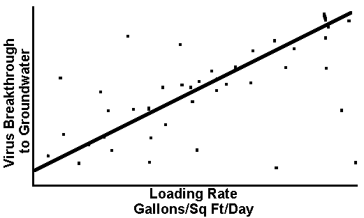
Research summarized by Yates (1987) and others clearly indicates a positive
relationship between hydraulic loading rate and the breakthrough of viruses
to the groundwater. In 1991, under a grant from EPA, the Buzzards Bay Project
commissioned our department to research the literature relative to vertical
separation and horizontal setbacks to determine whether there was a technical
foundation for increased setbacks (generally 100 ft to wetlands and watercourses)
that had been adopted by many towns on the Cape and in the Buzzards Bay
Watershed. We determined, using a compilation of studies and a correction
factor calculated using a study conducted by Dr. James Vaughn in the similar
soils of Long Island11,
that a loading rate of 0.75 gallons per square foot per day (with 5 ft.
vertical separation of leaching facility to groundwater), would give reasonable
assurance in most situations that viruses would not enter the groundwater.
In the event that viruses did enter the groundwater, we recommended that
the horizontal setback distance requirement of 100 ft. be maintained. Pleasantly
coincidental was the fact that independently a loading rate of 0.74 gal/sq
ft./day for sandy soils was adopted in the revised Title 5 in 1995.
Controversy in the Issue of Virus Removal
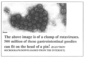
There is considerable controversy regarding the issue of viruses that
must be frankly confronted. On the one hand, many contend that public health
officials are unduly conservative in this regard, and their insistence
on vertical separation and horizontal setback requirements (discussed in
the next Module) impose unreasonable cost. Public Health Officials, on
the other hand, have the weight of history with polio epidemics of the
1950's, hepatitis outbreaks and periodic and recent outbreaks of Norwalk-virus-related
illnesses that compel them to "hold the line". In addition, the
adsorption of viruses onto soil is not a permanent phenomena. Intense rain
or a dramatic change in the effluent characteristics can cause viruses
to desorb and move (be entrained) downward in the soil column toward groundwater.
A take-home message one gets from reading the published literature is that
there are so many variables associated with virus removal from wastewater,
a conservative approach is warranted. Despite the controversy regarding
what theoretical removal target should be used, one issue remains clear.
Treatment for pathogenic viruses occurs primarily in the unsaturated zone
beneath the leaching facility, and maintaining the unsaturated nature of
this zone is essential. As Boards of Health are asked for relief from various
aspects of Title 5, it is clear that detail surrounding variances from
this aspect should be carefully scrutinized and only relaxed
when all assurances have been made that an equal degree of environmental
protection to that provided by Title 5 can be met. Some means to compensate
for smaller separations are presented later in context of basic treatment
facts.
| Want to learn more about virus persistence in Groundwater ?
Attached at the end of this module is a collection of reference
articles that, although rather dated, may give you an idea of the factors
involved in virus survival in groundwater. They were annotated by George
Heufelder and Susan Rask as part of another project. They are not mandatory
reading for the course, but are presented for the inquisitive among you.

|
A Short Word About Bacterial and Other Pathogens
You may have noticed that we have mentioned very little about the bacterial
pathogens. This is because studies conducted in sandy soils most common
to our area (including research conducted by our Department in Buttermilk
Bay, Bourne under the Buzzards Bay Project), strongly suggest that bacteria
are very effectively removed within short (less than 20 ft) distances from
a leaching facility located in sand, even if it is close to groundwater.
This is also presumably true about other potential pathogens, such as some
of the protozoa, since they are orders of magnitude larger and would hence
be strained out as effluent percolated through our soils. The danger in
this phenomena, however, is that fecal coliform (the majority of which
are Escherichia coli) are used as fecal indicators in both the shellfish
sanitation programs as well as for bathing beach waters. This means that
in coastal resource areas where septic systems are prevalent, the fecal
indicator may be absent, due to the effectiveness of the soil in retaining
them, but the viral pathogens could be present and go undetected. That
is, of course, until it the virus is digested with some tasty morsel of
shellfish that has filtered water containing viruses.
|
A word of caution for those reading this course
from outside of Barnstable County!
Bacterial and other pathogens remain an issue in areas shallow-to-bedrock,
or areas where fissures in the soil or rock allow for large passageways
that connect leaching areas with areas of wells or resource areas.
|
Ground Water Determination
With a good understanding of the importance of the area between the
bottom of the leaching facility and groundwater, only one set of questions
remains. Where is ground water? How do we determine ground water elevation?
and, How can we account for the seasonal variations in ground water elevation
in our septic system designs? Don't worry. As Board of Health members,
you will not have to know all the minute detail surrounding ground water
determination, but on the other hand, you should have a good idea about
the various ways it is determined.
Ground Water or Groundwater
a rose by any other name is still a rose. I will leave it to one of you
English or science buffs to tell the rest of us what is right, but the
code uses the former term throughout its length, while many publications
use the latter form. |
First things First - What is Ground Water?
The words "ground water" refers to "water found in cracks,
fissures and pore spaces in the saturated zone below the ground surface,
including but not limited to perched ground water"12.
Ground-water elevation is that elevation below which all
available pore space between the soil particles is filled with water as
opposed to air. It is also called the water table. Since,
as we have stated, the majority of treatment for pathogens occurs in the
area below the leaching facility and above the groundwater, it is crucial
that the groundwater elevation is accurately determined. To account for
the seasonal and year to year differences in groundwater elevation, Title
5 requires that the high ground-water elevation be
used in the design of a leaching facility. This prevents the design and
installation of a system in a "dry" year from having the unsaturated
zone under the leaching facility reduced below the minimum requirement
in a "wet" year. Similarly, in near coastal situations, the high
ground-water elevation determination and usage (as opposed to a single
observation of groundwater that might not represent the worst case situation),
prevents the infringement on the critical vertical separation distance.
The methods for determining high ground-water elevation are reviewed later.
So, How Much Unsaturated Zone Under A System is Enough?
If anyone tells you that they know historically where the vertical separation
requirement of 4 ft came from, they probably also have a bridge to sell
you. A wide range of values are reported to be effective for the removal
of pathogens. The truth is, that pathogen removal is not the exact science
we would like it to be, and this is reflected in the variability in states'
requirements for vertical separations. There are, however some consistent
references in the literature that suggest the appropriateness of the 4
foot vertical separation requirement, and Massachusetts joins at least
19 other states in this requirement. The additional 5-foot requirement
in coarse sands and gravel is appropriate considering the literature indicating
the reduced ability of coarse-grained sediments to retain bacteria and
viruses. In any event, the recent literature and recommendations made in
the Technical Evaluation of Title 5 are likely the origin of the four and
five foot separation requirement13
in the revised code.
One More Thing About the Unsaturated Zone or life in the fringe
It wouldn't be quite right to leave you with the impression that beneath
the leaching facility until you reach groundwater, you can achieve totally
unsaturated conditions that are ruinous to pathogens. The fact is that
there is an area directly above the water table or groundwater elevation
that contains significantly more water than in the majority of the unsaturated
zone. This is due to the fact that capillary action wicks water upward.
Thus the soil pores directly above the water table may be quite close to
saturation in a decreasing gradient with height. The area of not-quite-saturation
directly above the water table is called the capillary fringe
. The height at which the capillary tension on the water discontinues to
"pull" it upward is different for different soil types. A generalized
table is given here.
| Material |
Height in meters
that water can be
drawn upward from
water table |
| Sand |
0.05 - 1 |
| Silt |
1 - 10 |
| Clay |
>10 |
| Maximum |
>35 |
For
an illustration of the capillary fringe, click here
Groundwater is the result of precipitation (rain and snow) infiltrating
the soil. The annual amount of water that actually makes it to the groundwater
is referred to as the annual recharge. Where does the rest
go ? Well in the hydrologic cycle, some runs off into the ocean, some evaporates,
and some is taken up by plants and returned to the atmosphere (a process
called evapotranspiration). In Barnstable County, approximately
half of the annual precipitation actually makes it to the groundwater.
In some areas of Cape Cod and elsewhere, precipitation recharges a water
table that actually sets like a layer or lens on top of the salt
water table. The figure on the linked page attempts to help you visualize
this concept in cross section14.
The cross section shown is from the area between the A's. The cross section
of the area between the B's is a little more complicated because part of
the freshwater groundwater table actually is above a confining layer of
fine silt and bedrock. This later situation is quite common in other parts
of the state (where the groundwater table is confined by bedrock or dense
glacial deposits).
For
cross sections of Lower and Mid Cape lens, click here
A common misconception about the freshwater groundwater on Cape Cod
is that it is one big lens. In actuality there are six distinct lenses
throughout the Cape that are, to some extent, all hydraulically connected,
but recognizably distinct. If you are reading this and live in an area
outside of Barnstable County, we would encourage you read information on
groundwater from your area. An understanding of groundwater, and how it
connects or does not connect with water supplies and other resource areas
is extremely important in protecting the public health and the environment.
Groundwater - How do you find it ?
There's an old joke that starts with a musician from out-of -town running
through the streets of New York after his cab broke down on the way to
a performance. Violin in hand, late for his performance, disheveled and
nearly out of breath he stops an old man and gasps "mister, how do
you get to Carnegie Hall?". The old man sizes the musician up, looking
at the violin case at his side and says "practice my boy, practice".
How do you find groundwater? Dig my boy dig!
There are basically three ways to determine that all important high
ground-water elevation that is required for septic system design. You can:
1) Observe it (be there at the right time when the groundwater is at
its highest),
2) Estimate the high ground water using one of the approved methods outlined
in Section 15.103 (3)(c), or
3) Using soil characteristics and reference United States Geological Survey
(USGS) reference wells for corroboration.
Observing High Ground Water - Being at the Right Place
at the Right Time!
If you are fortunate to be able to schedule your percolation tests for
a time of year, and a year where you might expect the highest ground water
elevation, this method may be used to make the determination. Generally,
this method is used for areas where there is perched water (discussed later),
and some communities where perched water tables are prevalent insist on
this method. Even in perched water situations, however, this method may
not, of itself, give the appropriate level of certainty as to where the
maximum high ground water could come.
Estimating the Maximum High Ground Water Using an Approved
Method.
Historical groundwater fluctuations give us the best estimate of the
fluctuation we might expect at a particular site. Incorporating adjustment
factors from historical record yield the highest probability that we can
maintain the required vertical separation between the bottom of the leaching
facility and the groundwater. In Barnstable County a method has been
formulated, using historical water table fluctuations at over 52 wells
(nine of which were finally chosen for reference wells). The method is
described in detail in the Publication "ESTIMATION OF HIGH GROUND-WATER
LEVELS FOR CONSTRUCTION AND LAND USE PLANNING - A CAPE COD, MASSACHUSETTS,
EXAMPLE - UPDATED 1991" Published by the Cape Cod Commission in
cooperation with USGS (Authors Michael H. Frimpter, USGS and Gabrielle
C. Belfit, Cape Cod Commission). In summary, the method involves the following
steps:
STEP 1. Measure Depth-to-Water at the Test Site - This is normally
done in conjunction with the "perc" test. This is only valid
if the soils are sandy, so any observation of silt or restrictive layers
will invalidate the results.
STEP 2. Identify the Representative Index (reference) Well and Annual
Water-Level-Range Zone for the Test Site - The publication referenced
above contains four maps with delineations clearly indicating which reference
well serves the area where the property in question is located. Using a
colored gradient overlay, the maps additionally indicate the fluctuations
experienced by the groundwater within that area.
STEP 3 . Determine Current Depth-toWater Level for Index (reference)
Well - These data can be obtained from a number of sources that are
referenced in the publication (they are even on the CCC's Web Site). Choose
the water level in the reference well for the end of the month closest
to when the test was done at your site.
STEP 4 Determine Water-Level Adjustment - For this figure, another
set of tables provided in the document provide the potential water level
rise for any given observation.
STEP 5 Estimate Depth-to-High-Water Level at Test Site - This
is the easy part. Take the adjustment, subtract it from your observed value
at the test site, and away you go. You have an estimated high ground-water
value.
Confused enough? Actually, it is quite simple. Take some time to go
over a sample calculation that is provided in the document and I am sure
you will get it. In essence, all it is doing is incorporating historical
fluctuation trends into a time-fixed observation. Thanks Dr. Frimpter and
Ms. Belfit!
Is There Any Time When the Reference Well Adjustment
Won't Work?
We're glad you asked! The method previously described is inappropriate
to use where the groundwater level is affected by tidal stage. In the nearshore
area (within about 3-400 feet) the groundwater is primarily influenced
by the changing hydraulic head difference of the tide. The Concept is demonstrated
below. In the first illustration we can see a simplified version of what
is happening at low tide.
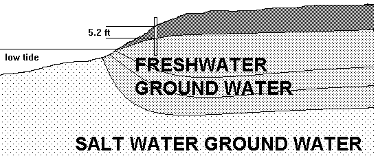
The freshwater groundwater is discharging near the shoreline and the
distance from the surface of the ground to the ground water is 5.2 ft.
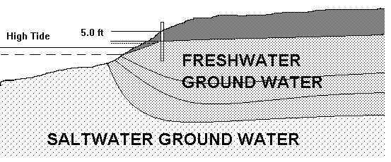
As the tide comes in the hydraulic head difference between the freshwater
ground water and the adjacent surface water changes. The resulting head
difference slow the exiting ground water, which now actually mounds up
a little. The result is a higher freshwater ground-water elevation (distance
from the ground surface to the groundwater is 5.0 ft). In many locations,
depending on the distance from the shore, the transmissivity of the soil,
and other factors, the observed elevation in groundwater will exhibit a
lag from the actual high tide. So, the best way to determine maximum high
ground water near the shore is to monitor the high groundwater elevation
hourly over a tidal cycle during a full moon high tide15.
Using Soil Characteristics to Determine Maximum
High Ground Water - Down and Dirty!
A substantial change in the Code since the revisions is the requirement
that a soil evaluation be performed by a Massachusetts Certified Soil Evaluator.
In addition to requiring information on a number of items (See Sections
15.100-15.107), considerable emphasis is placed on characterizing the
soils. By using a system of color evaluation called the Munsell System,
subtle changes in soil color can be noted. Some observed color changes
in the soil reveal a water table that fluctuates up and down, creating
alternately reduced and oxidized conditions. The resulting color patterns
in soils experiencing a fluctuating water table are called mottles.
In the Cape's soils, mottles are generally observed as orange or yellowish-red
blotches (due to the changing oxidation states of iron with the changing
oxidation-reduction conditions), against a gray background. The gray background
color is the result of reducing conditions that occur as soil remains saturated
for long periods of time. The benefit of using soil observations to determine
the depth of the water table is that it allows us to use the "trail"
of evidence left behind as water periodically rose to higher elevations.
If you get to see an observation hole, however, don't jump too quickly
to the wrong conclusion when you see the iron staining. Sometimes on the
Cape (especially in Orleans, Brewster and Chatham), I have seen horizontally-oriented
streaks of iron staining. These are sometimes caused by a soil inconsistency
that simply slows the downward percolating water and results in precipitation
of some iron. In general, these phenomena can be distinguished from high
ground-water mottles due to their horizontal (vs. vertical or blotchy)
orientation to the soil surface.
Special Cases in Ground-Water Elevations
It is not uncommon in some areas of Barnstable County (especially in
West Barnstable, Brewster and Orleans) to encounter a water table that
is suspended above the regional water table on a confining layer of silt
or clay. These water tables are referred to as perched water tables.
They are often observed as water weeping from the side of a deep test hole.
Closer observation indicates a confining layer of silt or clay just beneath
the weep site. The concept of a perched water table is demonstrated on
the next page. Perched water tables deserve special attention since the
water contained in them is considered groundwater16
for purpose of leach facility design.
In some situations, where the perched water observed is very limited
(a little trickle weeps out of the side of the test hole), the limiting
material can be "stripped out" for a distance of five feet around
the entire outer perimeter of the soil absorption system17.
A note of caution here. The "strip out" strategy should only
be permitted when the confining layer and the perched water is not extensive.
A increased number of test holes (more than two) are often necessary to
determine the extent of the confining layer. In addition, care must be
taken to assess the extent of perched water. This is done by observing
the soil mottling above the confining layer. If the mottling indicates
that the depth of perched water gets substantial (greater than 3 inches
depth) as indicated by observation or soil mottling, then a simple strip
out may not be sufficient to allow the occasional high volumes of perched
water to pass to the underlying ground water without hydraulically connecting
with the downward percolating effluent from the leaching facility. This
would result in saturated flow of the combined flows (perched water and
septic effluent) to the ground water; which by now, you know is not a good
thing. In cases such as these, the system should be designed using the
perched water table, adjusted for observation of any mottles, as the maximum
high groundwater.
For
diagram illustrating perched ground water, click here
Perched water will not be observed above every confining layer of soil.
In some instances, the confining layer is relatively small so that no water
collects on top of it. In other instances, the confining layer may have
a slope so that percolating water runs off of it. And still in other instances,
the confining layer may allow downward percolating water to pass through
it at a slower rate.
What to Do If the Extent of Perched Water is Questionably Problematic.
In some situations, and in consultation with the regional office Title
5 technical support person, it may be determined that an interceptor drain
can be used to drain away a perched water table (some folks call them "French
Drains" don't ask me!, collection drains, perimeter drains or diversion
drains).
For
diagrams illustrating the diffrence between perched ground water before
and after instalation of an intercepter drain, click here
Interceptor drains are used to convey perched water tables to the underlying
regional water table. They are used when the amounts of perched water indicated
either by observation or mottling are high enough that there is concern
that the downward percolating perched water will hydraulically connect
with septic tank leachate and result in less treatment.
The assessment of perched groundwater or confining layers of soil can
get pretty tricky. In some instances, the Health Agent and Soil Evaluator
must exercise his or her best professional judgment to decide whether the
small trickle coming from the side of the test hole is substantial enough
to require a design changes that count the perched table as the groundwater
elevation. Many agents prefer not to take any chances, and just require
a design that uses the perched table as the high ground-water elevation.
This is certainly the "safest" and most conservative from the
public health point of view. But we all know, there are those questionable
calls where a conservative call means substantial expense with questionable
return. In this event, remember that the staff at the regional DEP office
is available to consult with..
Seasonally-High Ground Water
Another term you may hear is "seasonally-high groundwater".
This term is generally applied to groundwater that is evident only seasonally,
and to some the term is synonymous with perched water table. The difference
between the two is that the term perched water table is usually used in
areas where there are coarse soils underlying the restricting layer. Seasonally-high
ground water is noted mostly in glacial till soils that may extend to bedrock.
Glacial till soils usually have a loose friable surface and subsoil. During
the spring snowmelt and rainfall, water percolates through these upper
strata, but collects on the dense, poorly draining hardpan beneath. Eventually,
the water will percolate through this poorly draining soil, but water is
frequently and seasonally observed perched on top of the hardpan. In these
situations, the seasonal high groundwater must be considered as the high
ground-water elevation for purpose of design. Seasonally-high groundwater
fluctuations often exhibit themselves with very obvious mottles, that are
evident even during the dry season. In these situations, where the seasonally
high groundwater table is near the surface, the system must generally be
mounded, using the percolation rate of the fine material underneath.
Applying What We Have Learned
Thus far, this module has reviewed the concepts and principles involved
in the vertical separation distances between the bottom of the leachfield
and the groundwater. The key points that you have hopefully learned are:
- that vertical separation is the most important feature for the treatment
for pathogens and that viruses, in particular, are inactivated in the unsaturated
zone under the leaching facility;
- uniform distribution of effluent across the entire infiltrative surface
of the leaching facility becomes more crucial for the treatment of pathogens
as you situate systems closer to the maximum high ground water;
- in a septic system where the effluent is distributed by gravity alone,
the biomat is the primary feature that allows for even and unsaturated
flow to the groundwater;
- the absence of a biomat can be somewhat compensated for by providing
even distribution of effluent by dosing or pressure dosing;
- the methods for determination of maximum high ground water
- an understanding of perched ground water
By now, you should understand that the vertical separation between the
bottom of the leachfield and the groundwater is intimately linked with
the loading rate. Remember loading rate is the amount of effluent you disperse
over a given area. In Title 5, this is generally expressed in gallons per
square foot per day (gal/sq ft/day). This brings us to a very frequent
request that Boards of Health are dealing with in the revised code: the
local upgrade approval request for either reduction in leachfield (which
increases the loading rate by virtue of decreasing the square foot area
that the effluent can be dispersed on) or the request to approve a decrease
in vertical separation. Notice we said "or". Section 15.405:
Contents of a Local Upgrade Approval (subsection 1(i)5)18
clearly indicate that the approval for both the reduction in vertical
separation and the reduction in leachfield size can not be just locally
approved (but may be the subject of a variance request). There is a very
good reason why request for relief from both vertical setback and loading
rate should come under a higher level of scrutiny. The reasons are summed
up in the following small table:
|
ACTION
|
RESULT
|
| Leaching field size decreases |
1)Loading rate in gal/sq ft/day goes up there is less area to take
the same flow)
2)Treatment per foot of passage decreases (see graph) |
| Vertical separation decreases |
1) Total treatment decreases because there is less vertical passage |
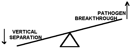
Double Whammy! If we could allow a decreased leaching field (25% reduction
allowed under a local upgrade approval described in Section 15.405
(1)(c)), and a decrease in the vertical separation,
we would be getting less treatment per foot of passage and
less feet of vertical passage. 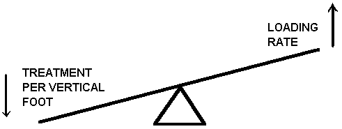
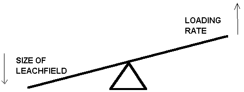
This information regarding the relationship between leaching field size
and vertical separation, should, however, make us feel a little more comfortable
about allowing a decrease in the leachfield size (up to 25%) if there is
greater than the required vertical separation. This is because,
although we have less treatment per foot of passage with the higher loading
rate, the greater vertical separation can compensate by providing more
distance for vertical passage before the effluent hits the groundwater.
To put it another way, if someone requests a local upgrade approval for
decrease leachfield size, the Board of Health can feel a little more comfort
that there will be an equal degree of environmental protection afforded
by the system, the greater the vertical separation that can be achieved.
What about local upgrade requests for reduction in the vertical separation
itself?
Well, we can see from the chart on the previous page, that decreasing
the vertical separation can only be compensated for by reducing the loading
rate. Decreasing the loading rate can only be done by increasing the leaching
area of the system. This would be an unreasonable request by the Board
of Health, given the already-more-expansive system requirements under the
revised code. So, in consideration of its importance, Boards of Health
should insist upon the proper vertical separation, even if it means installing
a mounded system.
But what if it is not possible to achieve the vertical separation?
What should a Board require to compensate for decreased vertical
separation in situations where the required distance can not be achieved?
Hold on to your seats - that is a complex question!
If the request for decreased vertical setbacks is far and away (greater
than 250 day groundwater travel time - or 250 ft on Cape Cod) from any
of the resources outlined in Section 15.211: Minimum Setback Distances,
then the threat of disease transmission is very limited. This is because,
even if some pathogens did make it to the groundwater, their persistence
would, within reasonable probability and based on the virus literature,
not exceed 200 days (the 50 was added for a safety factor). If it is closer,
the Board might want to be assured that higher loading rates could not
occur in localized portions of the leaching field and hence increase the
probability that viruses could reach groundwater. How could the design
engineer ensure that there would be no localized higher loading rates?
Remember our discussion of dosing? See page 13 of this module and Module
1. Here, in the situation where there is less vertical separation near
a resource, the Board must decide if the situation warrants the extra efforts
that will be required to disperse the effluent evenly over the entire leaching
facility. The pluses are that pressure distribution will achieve more even
loading from day 1 and will hence achieve better treatment. The negative
is that the system will undoubtedly require more maintenance and expense.
In addition, generally the design and installation requires more oversight
since pressure dosed systems are not common as of yet.
Well, I think we have sowed enough confusion for now. The next module
deals with horizontal setbacks. In it you will learn how the resources
are identified, and those critical landmarks to look out for. The self
test that follows should let you know if you have grasped the concepts
in this module.
Take
a self-test to determine your understanding of the Module 2 material
Return to Home
 You may wonder,
as you go through this module "Why am I learning all this stuff?".
While it's true that this course is probably showing you more than you
ever wanted to know about septic systems (or could ever discuss in polite
conversation), consider the following. When someone asks a Board of Health
for a variance, they are essentially charged with proving to the Board
that granting the variance will not materially affect the public health
and further, that the proposed system deficiency is compensated for somehow
by an action, design modification or extenuating site detail that provides
"a level of environmental protection that is at least equivalent to
that provided under 310 CMR 15.000"1.
How does a Board of Health fulfill their charge to protect the public health
and the environment by ensuring that this test is sufficiently met? They
either a) become savvy enough to understand the principles involved
and the technical foundation of those requirements, or b) they rely
on the proponent's claim that they meet the "test" and hope for
the best. If you chose "a", this bud's for you.
  There is perhaps
no more controversial subject relative to the treatment of sanitary wastes
than that of viruses. Viruses are mentioned here because the primary
treatment site for pathogenic viruses is the unsaturated zone under the
leaching facility (commonly called the vadose zone). Once
viruses reach the saturated conditions of the groundwater, there are very
few mechanisms that work at removing them other than time and distance.

